Introduction
Loop powered indicators have been used in intrinsically safe systems for some time, but 'nA' indicators which are non-sparking devices that may be installed in Zone 2, are less common. This article considers both types, but gives more attention to the less established 'nA' indicators which may be used to display the 4-20mA current flowing in hazardous area loops protected by any technique apart from intrinsic safety.
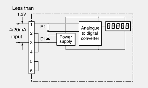
The basic operation of the majority of these indicators is illustrated by Figure 1
The operation of the indicator can be simply explained as follows: the 4-20mA current flows through the resistor R1 and the forward biased diode D1. The voltage across D1 is multiplied by a switch-mode power supply and used to power the instrument. The voltage developed across R1 provides the input signal to the analogue to digital converter which drives the display.
The major operational requirements of the indicator are to produce an accurate measurement and drop as few [1.5V] of the available line volts as possible. Indicators usually can incorporate backlighting and alarm facilities but these facilities are not discussed in this document. The increasing use of risk analysis techniques in determining the probability of explosions in plants where explosive gases may be present has resulted in the major part of the hazardous areas of plants being designated as Zone 2. Increased attention to avoiding leaks for ecological, economic and safety reasons have also contributed to enlarging Zone 2 locations. From the viewpoint of indicators this is fortunate since indicators are usually mounted in Zone 2 so as to minimise the risk to personnel. Human beings should avoid Zone 1 locations whenever possible since humans can present an electrostatic and frictional sparking risk, make mistakes and are susceptible to toxic gases.
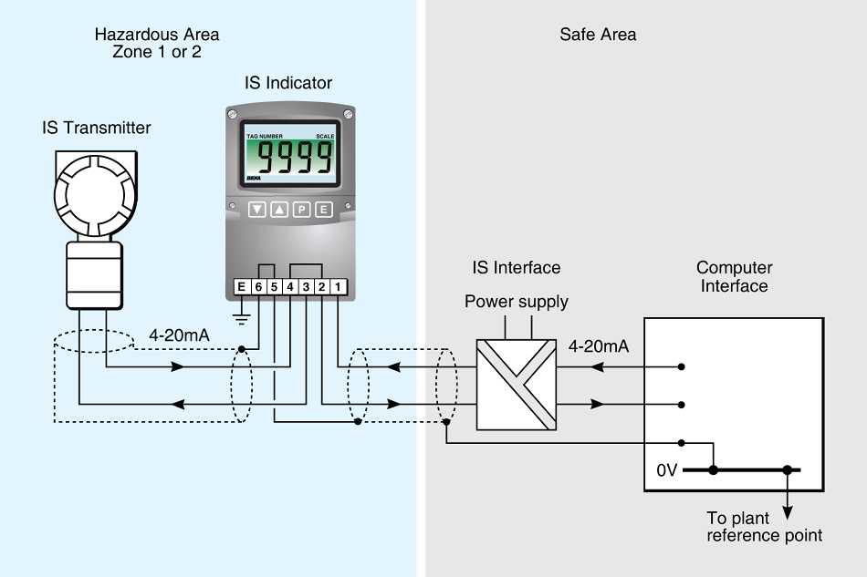
The use of intrinsically safe indicators
Intrinsically safe indicators are usually certified 'ia IIC T5' to IECEx and ATEX requirements. This enables them to be used in all surface industry locations and with all gases with the exception of carbon disulphide and ethyl nitrite, which have low ignition temperatures. Indicators are not likely to be mounted in a Zone 0 but the 'ia' certification allows them to be connected in a system part of which enters a Zone 0. The certification of these indicators normally designates the input terminals as satisfying the requirements of 'simple apparatus' and consequently they can be designed into or added to an intrinsically safe circuit without affecting the safety analysis of the circuit.

 Download this article in pdf format